Weatherproofing homebrew GPS kit (part 2)

Holland Park Umbrella

By taping it to the underside of an umbrella. On a gloriously sunny afternoon.

This afternoon I spent an hour wandering around the picnic-ers and sunbathers in Holland Park whilst carrying an umbrella.

During that time one child exclaimed loud enough and close enough for me to engage him in conversation (and an explanation); one woman gave me a look and a smile; and two men who had just thrown a stone at a pigeon told me it wasn’t raining. The latter also got an explanation.

On this occasion, the explanation has something to do with this.

Holland Park umbrella

Weatherproofing homebrew GPS kit (part 1)

So, I spent most of the day prior to the Ikon walk wrapping GPS modules and Arduino microcontrollers in plastic bags.

Wrap 'em in plastic

This is not an ideal solution to the ongoing challenge of protecting electronics from the weather! Since having one of my GPS modules stop working on the Fermynwoods residency, I’m also increasingly aware of needing to protect the units from the mild battering they get every time I use them in a workshop or for an event.

Time to invest in some proper protection.

After a bit of a search around, I found someone had been kind enough to share the files for a 3D printed GPS case on Thingiverse and thought it would be worth giving it a try…

3D printed GPS case

3D printed GPS case

It took about 30 minutes to print out the case. It needed a bit of knife work to trim off ‘squidgy bits’ that were preventing it from closing properly and to open up the case above the misaligned aerial dot, but the end result was pretty much as hoped.

3D printed GPS case

One drawback is that it’s a nice snug fit. Fine if you’re going to leave the module inside the case, but trying to remove it involved a fair amount of prising with a screwdriver and this can’t be a good thing!

3D printed GPS case

Second time around I placed some plastic under the module before placing it inside the case. This helped a little by providing something to pull on, but still not a real solution. (I’d probably try some ribbon or something with less stretch next time.)

The other main issue for me is that this process is not really of a high enough standard for me to use in an art project. Fair enough if it was hidden away, but these are likely to be on view quite a lot, so I need to pay careful attention to the material and quality of finish.

It would also be nice to be able to find a streamlined solution, but I think a certain amount of bulkiness is probably a price I’m going to have to pay.

Plan B is, I think, to investigate an acrylic laser-cut case. I want a certain amount of translucency so I can see the status LED on the GPS module, but I think having the tech on view is also a good thing for workshop scenarios.

Stay tuned as the experiments continue…

Stripboard Arduino shield for programming ATtiny45 and ATtiny85

I’ve a pile of ATtiny85 chips to programme up for the landscape-reactive sashes I’m making for the walking festival this weekend. To speed the process I designed and made a programming shield.

Finished shield running the Blink sketch

The instructions are up on Instructables:
http://www.instructables.com/id/Stripboard-Arduino-shield-for-programming-ATtiny45/.

AA2A: production shifts up a gear and user testing commences

Aided and abetted by one Mr Catfood, today I launched into making two more of the wooden drums I’m building as part of the AA2A project.

Much bandsawing, nail-gunning and guillotining was interspersed with making a bracket to mount the servo on (who knew finding the right screw would be so difficult?! Respect to Sol for the moment of genius that made her think of terminal blocks!) and then testing the resultant tappity object.

microcontroller and servo

testing, testing

In other news: Jupiter, the moon and Venus are looking rather marvellous from my back window at the moment.

Jupiter Moon Venus

Initial results from the Chin Up Chapeau

Having made a hat to measure my posture as I walk around different parts of the city, I’ve spent the last few days testing it and getting a feel for what sort of results it produces.

Chin Up Chapeau - initial results.

Diagram showing position, direction I'm facing and the angle of my head. Click for a much larger version...

Pretty much exactly as I was expecting really, which is probably a good reason to avoid drawing any sweeping conclusions from it – at least until I’ve got to the stage where I collect data without being aware that I’m doing so…

On the plus side, it does reveal lots of unexpected things – posing yet more questions in the process – and that, I believe, is the sign of a good tool!

For these renderings, green represents a neutral head position, with the pointer getting redder as my gaze is lowered. Here are some noticings:

The lower, horizontal section shows me walking along a fairly busy road: eyes front, head direction and angle reasonably constant. The upper section is along a footpath next to a river: my interest is drawn in all sorts of directions and this is shown by the inconsistency in pointer direction and colour

Close-up of a high interest area - head angle changes a lot, as does the direction I'm facing

Head angle decreases slowly as I approach the High Street, but returns to a neutral position a lot quicker as I leave it behind me

High Street Mode gets switched off as soon as I go into the Post Office, on another day it fades slowly as I walk away.

It’s becoming apparent that I need to include some sort of calibration so that I can more reasonably compare tracks from different walks. Currently, differences in how I’m wearing the hat are too easily read as differences in head angle when I put all the traces on the same diagram.

I’ve also expanded the arduino code so that I log date, time, latitude, longitude, altitude, course, speed, bearing, pitch and roll. I think there are some very interesting potential correlations to investigate (for example: when my head angle decreases, do I also walk faster?) and, whilst I may not be investigating them right now, I want to make sure I’ve got the data when I do!

Introducing the Chin Up Chapeau

[or the Shin Up Shapeau. Or the Chin Up Chap! Oh!]

The Chin Up Chapeau

I’ve been thinking a lot about how my posture changes in relation to whereabouts I am as I walk around Birmingham.

As I approach what I perceive to be high risk areas I believe I adopt a significantly more defensive stance: lowering my gaze and stooping slightly. Of course, there are hunches and there are hunches…

I made the Chin Up Chapeau to measure the angle of my head and log it along with locational data so I can see exactly how my posture relates to space. Do I really stoop, or is it, y’know, all in my head? Where are the danger zones? Are the boundaries clearly defined?

The Chin Up Chapeau sports a gps receiver [EM 406a], a tilt-compensated compass[CMPS10], a logging device [OpenLog] and an arduino clone microcontroller [RBBB] along with a few other accoutrements like a soft switch and an indicator LED.

There are still a few niceties to be sorted out, but here’s a visualisation of a quick walk last night:

Head angle, bearing, location ...and a loaf of bread from the Co-op

I’m going to log data as I walk around the city, but I’m very aware of how easy it would be to ‘fake’ the outcomes to match what I think they should be.

Or perhaps I’ll be concious that I’m watching myself and instead make an effort to keep my chin up at all times…

At the very least I now have an electrically heated hat to keep me cosy!

Dust: tech write-up

Now we’re the other side of Dust and safe from dropping any major spoilers, here’s a quick overview of how the Dust Balls were put together.

Dust balls? Here’s an extract from the explanatory text Hannah’s published on her blog:

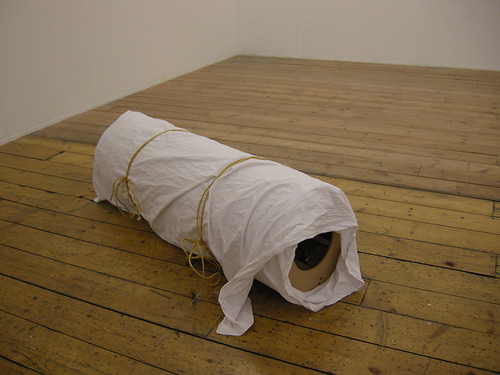
The Dust Balls are large fragments of the city. They are formed out of open source electronics, clay, hope and optimism. They begin by introducing themselves to the listeners, and instruct them to point the device in different directions in order to ‘pick up’ stories of individuals in the areas surrounding them. Depending on the timing and direction in which you are facing, different stories will be heard.

They are heavy, and designed to be listened to by two people at once – the weight and bulk of the object meaning that two are required to support it. The two people sharing each experience of overhearing the stories should be strangers.

Quite a design brief there, with some technologies I’d never worked with before (audio and direction-sensing). Fortunately I know where I am with clay!

Fragments of the city

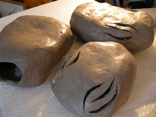
The finished Dust Balls

There’s a whole other post-worth of talk about the whys, wherefores and processes relating to the clay, but this post is about what went inside the Dust Balls.

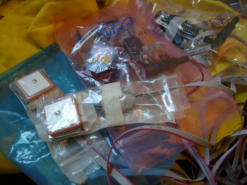
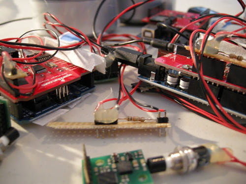
Short answer: lots of electronics.

Dust bunny brains

Location, location, location

Once we’d decided to site the Dust event on top of the Vyse Street car park, I spent several hours up there over 3 or 4 visits after work. We didn’t have much in the way of lead-in, but this was time well spent getting to know the feel of the location and details such as how loud the ambient noise of the traffic below is, how busy the car park is at that time and generally getting to know the lie of the land.

View from the top deck of the car park towards Snow Hill station and Colmore Square.

From here we were able to locate the 5 story threads that Hannah had written amalgamating objects and memories submitted by different contributors.

Thread 1: a visitor to Birmingham is reminded of being in love; Thread 2: a man feels like a boy as he listens to a recording of the grandfather he never met; Thread 3: an office-worker battling deadlines and spreadsheet puts a hand to the pocket containing one of his son's toys; Thread 4; a victim runs through the city streets at the feet of the tower blocks; Thread 5: a friend bearing a gift walks purposefully towards the hospital.

Working from a tracing from a fold-out A-Z map of Birmingham, I drew out the segments for each thread and used a protractor to get the bearings for the boundaries between threads. This working diagram was then orientated to North and taped to the table-top in preparation for testing the the next stages…
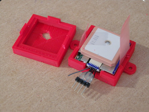
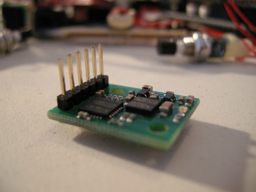
Locating story fragments

The compass module

After some research into different options, I decided to use this CMPS10 tilt-compensated compass module. The tilt compensation was important (since we couldn’t guarantee the Dust Balls would be held horizontally) but it was also selected because of the range of communication methods (serial, I2C, pwm) and the documentation and example code available. Given the lack of time and my lack of coding chops, this is the sort of bet-hedging that was required!

Compass module

It was easy enough to get the compass module working with an Arduino using the example code. I initially tried serial communication, but I couldn’t get this working via the NewSoftSerial library when I came to combine it with the mp3 shield.

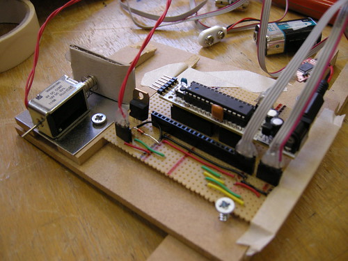
The switch to I2C communication required the addition of a couple of pull-up resistors, which I made into a stripboard ‘shield’ that I could plug into the Arduino stack.

I2C and reset 'shield'

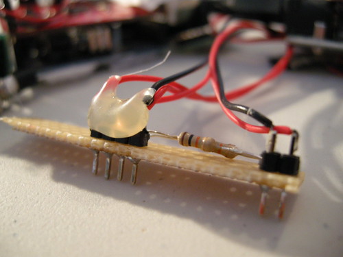
This made things a bit more robust for placing them inside the Dust Balls, as well as being a nice convenient modular approach.

I also added in a push-to-make switch between the ground and reset pins. This would allow me to place the the electronics at the back of the Dust Ball where they wouldn’t interfere so much with the compass readings, but to still have reasonable easy access to reset the kit between users.

mp3 shield

The remaining component of the set-up is the mp3 player shield. I used this one from SparkFun, and it worked, although I may well choose something different next time around…

Dust bunny innards

The main thing to be aware of with this shield is the lack of a line out. There’s a headphone socket and somewhere to connect a speaker, but using an amplifier without also adding in protection against electrostatic discharge runs the risk of frying the audio chip. We’ve been lucky so far using portable speakers in the headphone socket, YMMV and you have been warned.

When using these shields you also need to be careful to install the SDFat library correctly (only the ‘SdFat’ folder from the zip file) and ensure you make the necessary changes to the Sd2PinMap.h file as documented in the mp3 player example.

The comments on the product page are well worth a read through too.

Anyway, I got it working eventually…

et enfin

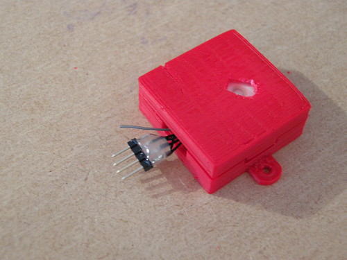
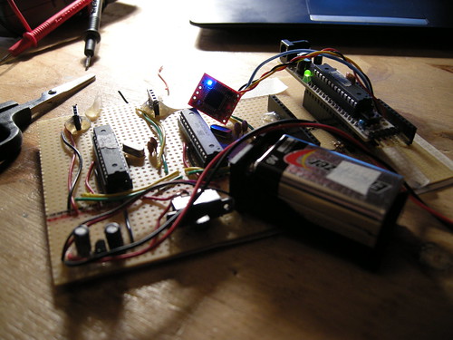
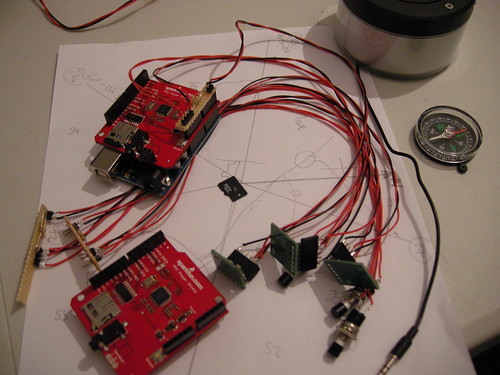
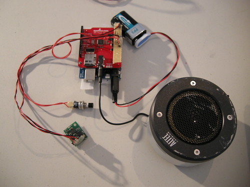
The final stack looked like this:

Stack: Arduino, mp3 shield and I2C/reset gubbins

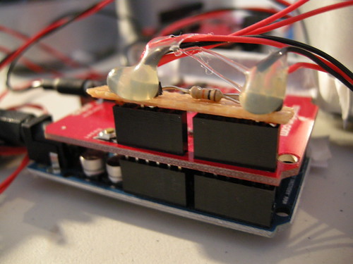
Arduino Uno, mp3 player shield and homebrew I2C/reset shield, also connected to the compass module and the portable speaker. All powered with a PP3 9 volt battery connected to the Arduino’s power jack.

I added in some hot melt glue to protect the soldered joints that were prone to flexing and breaking and also used black insulation tape to cover over some of the power LEDs (I didn’t want the Dust Balls to look like they were powered by Kryptonite!).

Strips of velcro were used to hold the components in place during use, whilst still leaving them removable when required.

The code takes its main functionality from the compass and mp3 player examples, with some logic to select which audio track to play depending on which direction you’re facing and what’s been played before.

As ever, there’s room for improvement, but hopefully there’s enough here to get you started with your own projects. There’s also a set of photos from the make on Flickr.

We will not be afraid to get our hands dirty.

We will make and share our own tools as appropriate.
We will collaborate.
We will be generous.
We will be porousexcerpt from the Splacist Manifesto 2.0

Mapping now possible

There’s still work to be done, but over the last couple of days I’ve finally been able to replicate the traces I’ve previously been using two sat-nav type devices to make, using my home made Arduino-based system instead.

This feels good.

From here I can go anywhere.

The iPaq-in-each-hand technique

The 3-arduino-2-GPS-modules-and-a-micro-SD-logger-hidden-in-a-bag-so-as-not-to-scare-people-too-much technique

Whilst I’m using this set-up for logging, there’s painfully little feedback on whether things are working as they should, however once I return to the UK I’ll be experimenting with using it to drive various visible and/or audible things and of course putting it inside the Colony creatures.

In the meantime though, I shall be testing, testing and more testing.

GPS parallelograms

Not entirely what I’d expected when I went out to test the homebrew GPS system today…

Several hours meandering around Central Park rendered as 10,000 small lines mostly aligned in one of two directions

What’s going on there, then?

Ups and downs

Along with many other freelancers, I’ve been using the bank holiday season to concentrate on getting some work done. One of the major tasks on hand at the moment is to further develop my Colony project ready for the Platinum sharing event.

My first attempt at reading two GPS datastreams into an Arduino microcontroller over serial ran into some strange issues, so I decided to investigate I2C just to make sure I didn’t spend an incredibly long time barking up the wrong tree trying to make the serial version work.

Well, it’s been a steep learning curve and I’m truly indebted to the likes of GB, Ben and Adrian, but I we have now got the basics of some code working!

My coffee table currently looks like this:

3 RBBB microcontrollers, 4 breadboards, 2 GPS modules and lots of wire

Each of the GPS modules has a slave Real Bare Bones Board reading its data and sending longitude and latitude values over to the master RBBB when requested. The master RBBB reassemble then does a quick comparison between the two values to give a measure of difference.

I left this set-up logging the difference between the two GPS positions whilst I went out for an hour or so, and this is what I returned to:

The measure of difference (y-axis) plotted against time (x-axis, very approximately in seconds)

The kit is on a table not particularly close to the window in my attic flat, so there’s GPS reception, but I wouldn’t expect it to be particularly stable. That said, the graph above struck me as being very regular somehow: not as random as I had expected.

I’m wondering if the peaks correspond to the ebb and flow of the satellites overhead. Is that likely?

edit:Scratch that; wrongheaded. What would affect one GPS module and not the other?


Copyright and permissions:

General blog contents released under a Creative Commons by-nc-sa license. Artworks and other projects copyright Nicola Pugh 2003-2024, all rights reserved.
If in doubt, ask.
The theme used on this WordPress-powered site started off life as Modern Clix, by Rodrigo Galindez.

RSS Feed.