What might be

I’m always trying to track down this list to refer to – putting it here so I know where it is…

Also now wondering how it might function as a daily to-do list?

Drawing on a four-year development programme in 120 schools, the QCA identify five elements of creative learning experiences:

  • asking questions
  • making connections
  • imagining what might be
  • exploring options
  • reflecting critically

source

Reflective armband teardown

A quick teardown of a Poundland reflective armband, because I’m doing wearable electronics on the cheap at the moment and this has got a few useful components inside…

Flashing and reflective armband, from in amongst the cycle stuff in Poundland. Comes in silver and fluorescent yellow. I've also seen a variant of the packaging that's orange.

Elasticated Velcro strap attached to reflective band with 4 LEDs mounted along its length. Click the switch once to make the LEDs flash, a second time to have them on continuously and a third time to switch them off.

What you get when you open it up...

You can liberate a fair bit of Velcro from the strap. Elastic is also used to make a pouch to hold the battery.

The momentary switch isn't much to look at (you were going to wrap it in fabric anyway, weren't you?) but it makes a good click when you operate it. Nice feedback.

The battery clip is minimal, but does the job... Also it has a battery in it!

The battery clip is also the main PCB. You can remove the wires and connect your circuit to either of the corner tabs (+ve) and Vss (-ve/GND)

I used the battery and battery clip to power the LEDs from 3 bike lights in this superhero cuff project. The velcro and elastic were re-used as a strap to hold it in place and the switch was used to trigger the different flashing patterns for the LEDs.

assembling

POW!

Blinking bats

A second slice of LED-based Halloween goodness.

Blinking bats from nikkipugh on Vimeo.

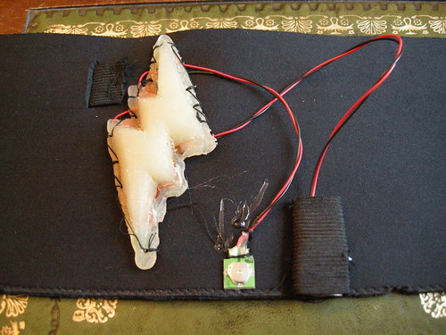
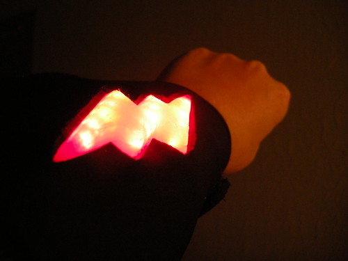
These bats will be part of my attire for later today, but they’re really quite pleasing just by themselves!

A really simple build using an Arduino-based Real Bare Bones Board, some cardboard, some insulation tape some wire and 14 LEDs.

Here’s the code:

/*
blinking bats
nikki pugh 30th October, 2010
Attribution-NonCommercial-ShareAlike Creative Commons
Powers LED eyes for a colony of bats, blinking them in a random sequence at random intervals
http://npugh.co.uk/blog/blinking_bats/

LED pairs with 330ohm resistors in series, connected between the output pins and ground.
*/

int colonySize = 7; // How many bats do you have?

//control pins for each bat

int bat1 = 2; // bat1
int bat2 = 3; // bat 2
int bat3 = 4; // bat 3
int bat4 = 5; // bat 4
int bat5 = 6; // bat 5
int bat6 = 7; // bat 6
int bat7 = 8; // bat 7
int bat8 = 9; // bat 8
int bat9 = 10; // bat 9
int bat10 = 11; // bat 10
int bat11 = 12; // bat 11

int gap = 3; // gap before selecting next bat to blink
int colony[] = {bat1, bat2, bat3, bat4, bat5, bat6, bat7, bat8, bat9, bat10, bat11}; // Put bat IDs into an array
int batSelect = 1; // your bat selection variable - used for selecting a bat ID from the above array
int blinker = bat1; // the bat selected to blink
int i = 0; // counter for start-up blinks

void setup() {

randomSeed (analogRead (0)); //read from the (unused) analogue pin to get a value to seed the "pseudo-random number generator"

pinMode(bat1, OUTPUT); // set pins to be outputs
pinMode(bat2, OUTPUT);
pinMode(bat3, OUTPUT);
pinMode(bat4, OUTPUT);
pinMode(bat5, OUTPUT);
pinMode(bat6, OUTPUT);
pinMode(bat7, OUTPUT);
pinMode(bat8, OUTPUT);
pinMode(bat9, OUTPUT);
pinMode(bat10, OUTPUT);
pinMode(bat11, OUTPUT);

}

void loop() {

for (i = 0; i< 3; i ++) { //blink all bats' eyes at start-up digitalWrite(bat1, HIGH); digitalWrite(bat2, HIGH); digitalWrite(bat3, HIGH); digitalWrite(bat4, HIGH); digitalWrite(bat5, HIGH); digitalWrite(bat6, HIGH); digitalWrite(bat7, HIGH); digitalWrite(bat8, HIGH); digitalWrite(bat9, HIGH); digitalWrite(bat10, HIGH); digitalWrite(bat11, HIGH); delay (200); digitalWrite(bat1, LOW); digitalWrite(bat2, LOW); digitalWrite(bat3, LOW); digitalWrite(bat4, LOW); digitalWrite(bat5, LOW); digitalWrite(bat6, LOW); digitalWrite(bat7, LOW); digitalWrite(bat8, LOW); digitalWrite(bat9, LOW); digitalWrite(bat10, LOW); digitalWrite(bat11, LOW); delay (200); } digitalWrite(bat1, HIGH); //all eyes back on again digitalWrite(bat2, HIGH); digitalWrite(bat3, HIGH); digitalWrite(bat4, HIGH); digitalWrite(bat5, HIGH); digitalWrite(bat6, HIGH); digitalWrite(bat7, HIGH); digitalWrite(bat8, HIGH); digitalWrite(bat9, HIGH); digitalWrite(bat10, HIGH); digitalWrite(bat11, HIGH); while (true){ // infinite loop gap = random(1, 5); //wait some seconds before selecting next bat delay(gap*1000); batSelect = random (0, colonySize-1); //select a bat at random blinker = colony[batSelect]; digitalWrite(blinker, LOW); //blink delay(200); digitalWrite(blinker, HIGH); } }

Sonar goggle detector

Since some friends went on a bat and moth walk (and I’d idly Googled bat detector kits) I’ve been curious about building my own bat detector.

A few things came together and we ended having a lot of fizzPOP conversation about bat detectors. Then I started work on a school project for which an ultrasound detector would be rather nice.

It was kind of inevitable that I’d make one then!

Working from Tony Messina’s Simple Bat Detector project, I gathered together the basic components and tonight managed to get a breadboarded prototype working.

It occurred to me that building something that reacts to ultrasound may not be the easiest of circuits to test… Fortunately, I had some sonar goggles to hand and the detector reacts to them!

Breadboarded circuit with sonar goggles looming overhead

Breadboarded circuit with sonar goggles looming overhead

sonar goggle detector from nikkipugh on Vimeo.

Mr Mabbett also suggested placing the detector near a TV set (which I don’t have) or some jangling keys (which I do!) to test it. There are some good clicks coming from the keys test too, so next step is to get the circuit soldered up onto stripboard and into an enclosure of some sort.

As well as the schools stuff – where we would be using the detector to reveal sounds beyond our hearing – I’m interested in running workshops for people to build their own detectors. I also have some crazy game ideas…

Third party nunchuk plus Arduino

I’ve just got an Arduino to read data from a cheap third party wii nunchuk controller.

Because it wasn’t a genuine controller, it had 5 wires instead of 4 and the colours didn’t match with the tutorials [windmeadow] [TodBot Bionic Arduino class 4, pdf] I could find online.

I had to do a bit of experimentation to find out what went where. Recorded here in case it helps someone and for when, inevitably, I try and do it again in a few months’ time…

Bad photo of something I'm very pleased to have got working :)

Bad photo of something I'm very pleased to have got working :)

Wires

So, not only are there 5 wires instead of 4, but the colour coding is very different too. Opening up the case to the nunchuk and looking at the PCB shows some convenient labels:

GND – brown
SDA – red
SCC – yellow
VDD – blue
also
J1 (seems to be connected to VDD) – white

I managed to break off the white wire at the PCB whilst I was prising off the hot melt glue to look at the labels, and the following worked without re-connecting it…

Code

This post on the Arduino forum shows edits to make to Todbot NunchuckPrint sketch in order to get it to work for third party controllers.

Build

After testing on a breadboard, I soldered the wires to some headers for ease of use later.
With the above code red goes to Analogue 4 and yellow goes to Analogue 5. (Either connect the other two wires to GND and 5V pins, or the code allows for blue to Analogue 3 and brown to Analogue 2.)

And then…

Haven’t quite figured out what I’m going to do with this yet!

We need questions. We need answers.

I’m working on a massive Creative Partnerships project in a Leicestershire primary school with several other practitioners from various disciplines including, music, dance, architecture, story-telling, illustration and greenwood structures. Our brief: to make sure the staff can do what we do after we’ve gone.

We’re starting off on two threads of enquiry. One is to look at how we can encourage more imaginative play amongst the foundation level classes (3-5 years old) and the other is nominally working with years 3 and 4 (7-9 years). I say nominally, because actually I think we’ve discovered it’s more about exploring how the teachers can move away from teaching for a specific outcome and move more towards child-led learning where the outcome comes out of the process.

Last week this message was delivered in assembly:

The message delivered to the pupils last week

The message delivered to the pupils last week

On Friday the pupils worked with some of the practitioners on brainstorming their initial ideas and questions.

Tomorrow I will go in and liaise.

Today I am trying to plan the day without actually planning the day.

It’s counter-intuitive and a bit scary, but we need questions and then we need answers. In that order.

hippo joy

hippo joy from nikkipugh on Vimeo.

I’m liking this circuit-bending stuff. It’s making me do things I don’t want to do.

The particular comfort zone edges I’ve noticed are:

  • Restraining myself from immediately unscrewing the back and tinkering with the innards without having properly explored what the ‘normal’ behaviour is first. I must make more of an effort to document this too.
  • Choosing the 3 or 4 bends from several that I’ll try and work with. This is usually a balance between the “awesome!” and the practicality of getting wires and soldering irons where they need to get to. I ‘lost’ a really nice bend in the hippo – the behaviour changed when I soldered the switch wires onto the board. I’m starting to get into the habit of making audio recordings of the initial noodling noises. [audio:http://npugh.co.uk/media/hippo.mp3]
  • Revising the previous decisions, based on what switches you can accommodate in the shell.
  • Making the first incision. Usually my electric drill is hilariously large compared to the toy I’m working on: one of these days the toy’s just going to disintegrate. It’s also a very definite point of no return.
  • I’m slowly getting better at drilling holes a few sizes too slow and then taking them up to size with a file. Neater results, but there’s still room for a lot more improvement. I’ve also started thinking a bit more about the feel of the switches – adding in rubber o-rings to cushion body contact points etc.
  • Similarly for the first solder, but given extra edge by the memory of all the circuit boards I’ve managed to kill in the past.
  • I’ve circuit-bent a few toys now, all with similar push-to-make switches and body contacts. An important edge is coming up where I’ll have to learn new stuff. With the hippo bend I made myself repurpose the existing switches. It’s a bit of a bodge, but it was worth the brain-wracking to come up with a (hopefully more than temporary) solution that a) works and b) is satisfying in the way that it looks and touches.

A Flickr set of images showing the hippo’s internal gubbins is at http://www.flickr.com/photos/nikki_pugh/sets/72157622183430094/detail/

extra wires and re-purposed switches. also masking tape.


Copyright and permissions:

General blog contents released under a Creative Commons by-nc-sa license. Artworks and other projects copyright Nicola Pugh 2003-2024, all rights reserved.
If in doubt, ask.
The theme used on this WordPress-powered site started off life as Modern Clix, by Rodrigo Galindez.

RSS Feed.