Building the Orrery
For the last 10 months or so I’ve been building the Orrery – an electromechanical device that, ultimately, is powered by someone making a journey by bike. And by someone left at home wondering how they’re getting on.
At the core of the Orrery for Landscape, Sinew and Serendipity project, the Orrery is intended as a way in to talking about themes of effort, landscape, weather, bodies, home and connectedness that perhaps get tidied away when we use tools such as online map-based trackers to follow someone’s progress.
As I embark on the phase of the project where I’m meeting up with various people to discuss the potentials wrapped up in the Orrery, I wanted to look back and retrace the journey of its making. There’s been a lot of making. In keeping with the theme of making the effort visible, here’s an overview of how the Orrery came into being…
~~~~~

Most of the development work was done through a residency at Wolverhampton School of Art. This gave me access to tools, knowhow and a bit of space in which to work – things you learn to value when typically you’re making stuff in your front room!

The pilot project from a few years ago had taken the form of a person-sized box with a sort of porthole at chest height that you peered through to see the components levering, spinning and glowing inside. This time around I wanted to keep the act of peering in order to look inside, but shift to a smaller form that was more reminiscent of a locket.
Not being entirely sure if this would work, I started on some maquettes out of paper and masking tape.

This showed enough promise that I decided to develop this approach further however, after some time contemplating curvy bottoms, I decided that rather than having a shape like this that would then also need a plinth with a matching curve in which to stand, I would amalgamate both aspects into the bottom half of the Orrery.
More cardboard required!


Here’s the new strategy for an all-in-one rectangular base taking shape.
By now I’ve also switched to building up the form from a series of flat sheets. This was for some very practical reasons relating to what I would actually be able to build with the resources available …but also the echo of contour lines was rather nice too.

I needed to figure out how I was going to join the layers. I couldn’t glue them because I would need access in order to instal, remove and tweak the various electrical and mechanical components that would be going inside the Orrery.
I still didn’t know exactly what these components would be, and I was struggling to visualise the layout working with this model which was about of a quarter of the size of the final thing.

More cardboard?
No. I decided to bite the bullet and make a full-size model out of MDF. I knew the final version would be made out of plywood, but couldn’t afford to pay for two lots of that if I messed up, however I figured that making a model out of cheaper MDF, would pay for itself in time saved staring at cardboard and trying to scale things up in my mind’s eye.
I wouldn’t be cutting layers of MDF with a craft knife though. This was a job for the CNC router, and that meant drawing digital outlines of every layer so that the machine had some cutting files to work from.

A bit of jiggery pokery to get from open source software to the file format required by the router, and we were ready to start cutting.


STOP!
NOT THERE!
WHY IS IT CUTTING THERE?!
Oh dear, the router was having all sorts of problems trying to cut out the sheets. Bits were snapping off and jamming, then, just when we thought we’d got on top of that, it started cutting things out in random places, ruining the sheets that it overlapped with. ARGH!
I didn’t get much out of the whole endeavour other than the shapes shown below. And the realisation that I’d have to reduce the thickness of all the layers by about half.

A trip to the sawmill to do some touching, feeling, squinting, imagining the future and costing up of materials:

Having confirmed what thickness the plywood came in, I tried a different approach for making the model – foamboard. The School of Art was about to close down for the holidays – Easter by this stage, I think – so I needed something I could work with at home.


With a bit of large format printing and a substantial amount of the foamboard stock from the art school’s shop (conveniently about the same thickness as the plywood), I spent some quality time with sharps and my biggest cutting mat.


Ooh! Nice! I like these moments when the tangibility of the project you’re working on takes a leap forward. I was kind of commited to it from a production point of view, but this model totally sold me on the layered approach from an aesthetic point of view – those forms just kept on giving as the light in my front room changed throughout the day.

I also got to play with it in the dark and with internal lighting. Sort of.
…And then, many photos later, it was time to start hacking into the layers and figuring out where all the other bits of stuff would go. Now I was working to full scale, I had the major advantage of being able to use the actual components.
This was particularly useful for the lid, which was to house several stepper motors. Without 3D CAD skills, the only way to figure out clearances behind the panel they would be mounted through was to try it.
Several times.


Back at the art school, I also started making some of the mechanisms that would go into the Orrery. Here’s a quick return mechanism that was particularly satisfying to make with a combination of mallet, chisel and geometry.


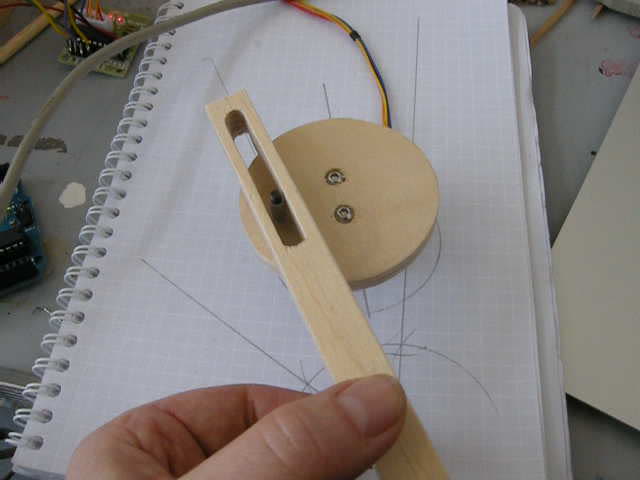
Sweet.
With application of a few more tools of the trade, the location for the quick return mechanism was decided:

With application of lasers, I added this to the collection too:

I spent some time trying to make a few components out of metal, but with access to workshops getting increasingly less straightforward (assessments approaching) I had to give up on that. Here are a few things that didn’t quite make it into the build:


Bits of the chain (from my touring bike) may or may not make it into the Orrery – I’m still pondering that one.
Meanwhile, back to the wood…
Time to bite the bullet, buy a lot of plywood, and get cutting!
Nope, wait! Measure twice, cut once…
Let’s look at those cutting files really closely before sending them to the router.


Printing out the layers helped me to catch a few snags, which were dealt with and then, then, it was time to send them to the router.
This time around I was using the FabLab facilities at Enginuity in Coalbrookdale. Phil the manager there knows his onions (and his cutting tools) so we got all the bits cut out without incident (and with only one mistake that had slipped through the net earlier).


The CNC routing leaves these little tabs to hold the parts in place until cutting on the machine has finished. Then you need to have at them with a Stanley knife to pop the cut parts out of the big sheet.
And then….


… a not insignificant amount of dremmeling to get rid of the tabs.

The layers looked good stacked up on top of each other, and the cunning plan for fixing them together worked effectively too.

There was still the question of how to join the top half to the bottom half, though. Ideally I would be able to do this without the need for a prop, as that would obscure the view into the Orrery. After a lot of searching around, I found these friction hinges. I couldn’t find the ones rated for greater torque available in the UK, so it would have to be a case of fitting them, building the rest of the lid and seeing what happened.


All good so far with the first few layers fitted…
…then of course I had to take them apart again…

More sanding.

And then a lot more sanding.
Now mostly working at Umake open access workshops, I spent several days sanding down the layers to get them ready for waxing and staining. A brief interlude in all the sanding (did I mention there was a lot?) was provided courtesy of Physics and these dancing piles of dust that appeared one evening:


Meanwhile, Kim had been working hard on the Raspberry Pi end of things that would take the data coming in from Jez and Mike’s creations and set the Orrery in motion.

Then came the time when I had to make some fairly irreversible decisions about the size of the containing box that everything had to fit inside. Determining vertical height first, then bandsawing slices off the top sheet to get length and width down.


The original plan for the sides had been to use laths of plywood to keep the edge-on effect, but I had to make the call that there just wasn’t time to do this and that I would instead use sheets on their sides to make the walls of the box.

Here are the panels freshly cut to size and with fixing batons being glued into place:

…and then, some time later, the magic moment when it’s all assembled and for the first time I saw the thing that up until now had only really existed in my mind’s eye!

Phew! That was the thing that I had wanted to build!
Onwards with the waxing and staining. Again Umake came in very useful with their large workbenches.


And assembled again:

A few extra details to finish off the main structure:

Very small – but also very strong – magnets.

Some channels for wiring.

And some confidently wonky props. (As it turned out that the friction hinges weren’t strong enough on their own to support the lid.)
.
.
.
Here’s a photo of a milliput bird resting on some grapes.

Yeah, so, that didn’t work out so well.
Next attempt: lasers!


Keep reading to find out how they turned out :-)
What else?
Lots of epoxy glue happened at about that time. Here’s a winding drum about to be fixed to a stepper motor hub:

And here’s the full set in position:

By now the main focus was on getting all the mechanical doodads installed and working properly. There was much attaching and removing of the lid, soldering, heatshrinking, drilling, knot-tying and even a few cable ties.

The hinges got some rubber shims out of the traditional material:

The timing belt was sewn and fitted:


Some somewhat more delicate sewing was done:

And a lot of string was strung:


The image above shows the lighting strip in place too. Here it is before it got its diffuser:

The Clacker was one of the last components to get made. I’d planned to get it cut at the same time as doing all the CNC routing at Enginuity, but we couldn’t get the files to read correctly, so I ended up cutting it ‘by hand’ on the bandsaw.

It just needed a little something extra to complete, which had me scratching my head for a while but The Draw of Random Bits of Stuff came up with a winner:

The birds came out nice in the end too:

And then that was pretty much it in terms of the build…
October 2015 to July 2016: a lot of prototyping and eventually using facilities across Birmingham, and in Wolverhampton and Coalbrookdale to gain access to the tools I needed. Not too many mess-ups, and an end result I’m proud of. …except it’s not quite finished yet as we still have a lot of work to do to get the physical structure functioning in response to various data sources.
We’re (we being myself, Kim Wall, Mike Cummins and Jez Higgins) going to keep chipping away at that over the next few months, which is when I’ll also be out and about recording some conversations with different people in response to the Orrery.
Below are a few teaser shots which I hope will entice you to come and see the whole of the Orrery when it is on display in Wolverhampton Art Gallery in October – watch this space for more details closer to the time.


