A recurring theme throughout this project has been the need to make my own tools. I suspect this is something professional framebuilders find themselves doing quite a lot too, although hopefully with a bit more finesse!
Still, if it gets the job done…
Job #1: Removing bearing cups
There are a couple of places on the donor bike where there are races to hold ball bearings: the bottom bracket, where the cranks turn; and the headset, where the steering arrangement turns.

Bottom bracket cup
I still want these functions in the new bike I’m making, even if the pedals can’t turn without hitting the ground and the front wheel can’t turn very far before hitting the frame. This means I needed to remove the bearing cups from the frame to keep them safe whilst I was hacking the surrounding steel to bits and then welding stuff back together again.
The cups are pretty solidly wedged into their respective parts of the frame, so trying to prise them out with a screwdriver wasn’t going to work. This needed a proper tool …well, not a proper tool, as I couldn’t afford it, but at STEAMhouse I have access to other tools, so I could make my own bearing cup remover!

A bit of work with the cutting disc

4 slits in a length of tube

Slightly splayed so the tube spreads out to be wider than the cup

And POP!
It took a few attempts to not overshoot, but once I got the knack it was easy to hammer out the cups.

You hammer on the other end of the tool and the splayed out fins catch on the edge of the cup

Cups removed and ready to be put somewhere safe
Job #2: Gripping tubes
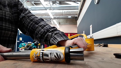
I’m going to have to do a lot of filing mitres into tubes so that they fit snugly up against other tubes. Thin-walled tubes held firmly in vices doesn’t tend to go well, so I had to make some tube blocks.

Tube block halves
Not a particularly tricky tool to build, just there’s so many sizes!

A not quite complete set of not quite complete tube blocks
Anyway, they seem to be doing the job well.

Mitred tube
Job #3: Bending stays
Here’s a reminder of the bike drawing I’m trying to make in 3D:

It’s not quite right, y’know…
That’s quite a lot of thingies that have to meet at the wheel axles.
Bicycle anatomy terminology breaks down a bit here, but I seem to have settled on calling them “stays” in a hand-waving kind of manner. Also I’ve had to make the executive decision that they will indeed go all the way to the wheel axles.
I’ve got some chunky tube to do the main bit of the frame, but I need something that comes out from that central plane, clears the width of the tyres and then joins on to the dropouts at the wheel axles. So I made a three-part jig so I could reliably replicate a suitable s-bend in some smaller diameter tube.

Side view: the tube is pushed up against a stop at the far right hand end, then clamped to the wall along the back edge, fitting behind the right-most pillar, which it is then bent out against.

Once the tube has been bent out towards the right, a plate with another pillar is slid up into position, clamped, and then the tube is bent back against it towards the left.

Here you can see the three parts of the jig and two of the bent stays

Quite nice

Birds-eye view with a wheel between them
The results were quite nice, but you can see from the above photo that it takes a fair bit of space for the stays to come back in to the centre line and the thicker tube. This would mean there would only be a small length of the thicker tube and I’d lose the effect of it stopping at the edge of the tyre.
I realised that I had been led astray by how I knew bikes were made, versus how this drawing of a bike looks. I ditched the jig and have instead switched to a much more clunky approach that will be a much better conceptual fit for what I’m trying to achieve.

An array of stays. Straight, this time.


